
Content Level: Overview / Implementation considerations
Principles and Suitability
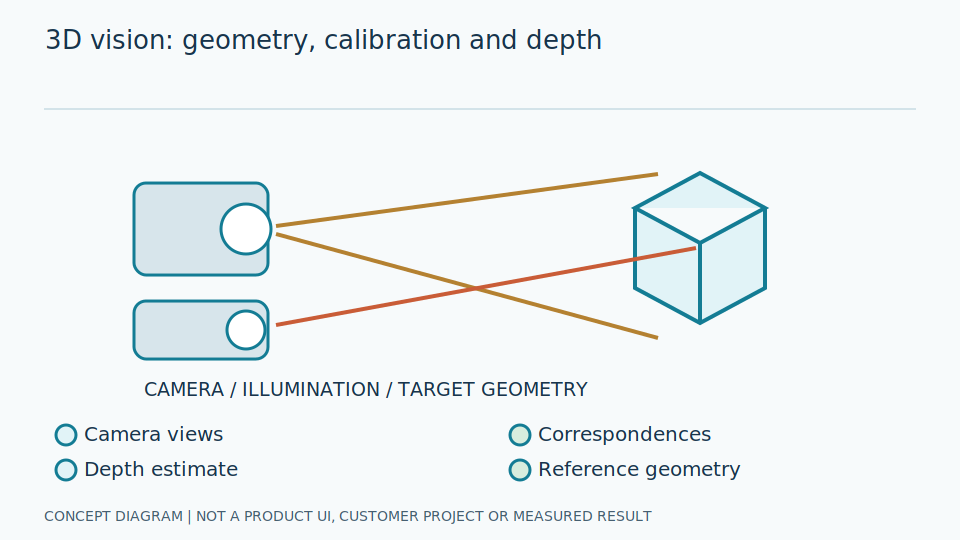
Stereo estimates depth from disparity between cameras; structured light projects patterns, while time-of-flight measures light travel time or phase. Each method has different ranges and surface limitations. Point clouds still need coordinate transformation and filtering before dimensional measurement.
Depth images add distance information but do not guarantee valid values at every pixel. Stereo compares corresponding positions in two images; structured light supplies patterns for geometric estimation; time-of-flight uses timed light responses. A method suitable for matte surfaces may struggle with reflective or transparent ones. Start with materials, distance and environment rather than selecting from the technology name alone.
Disparity is the position difference between matched image features. A point cloud contains three-dimensional points in a stated coordinate frame. Check units, invalid values and camera-to-reference-plane relationships before measuring. Filtering reduces noise but can change shapes. Keep raw points and document removal or filling so directly measured information remains distinguishable from additional estimation.
Scroll the diagram horizontally to inspect all details.
Illustrative Industrial Example
Illustrative design scenario: measure workpiece height on a conveyor using a depth camera calibrated against a plane and reference objects. Do not treat raw depth-image pixel values as millimetres without the required conversion.
Suppose reflective edges cause missing depth on a workpiece. An attractive colour display does not establish complete measurement data. Examine actual points used and excluded regions. Selecting only the highest point can let one noisy outlier determine height. Define surface summarisation and measurement regions consistently with the intended height definition, including an insufficient-points status.
Check reference planes and workpieces in the same coordinate frame. Measure perpendicular distance rather than blindly using the camera's depth axis. Test known reference objects at several positions and distances without creating hazardous conveyor conditions. Camera movement requires calibration reassessment. Confirm that colour regions selecting targets align spatially and temporally with their depth images; otherwise apparently correct crops may refer to different observations.
Study and Trial Workflow
- 1 Select the sensing principle according to distance, materials and ambient lighting.
- 2 Calibrate camera intrinsics and extrinsics and align coordinates with the workpiece.
- 3 Test several positions and heights against reference values.
Evaluation and Metric Definitions
Measure bias, repeatability, point completeness and uncertainty by distance. In stereo measurement, depth error grows with distance and can be reduced through an appropriate camera baseline or disparity resolution.
Bias is a directional difference from references; repeatability describes agreement under the same conditions. Tightly clustered readings can all be wrong, so report both with valid-point counts. Uncertainty explains contributions to incomplete knowledge of a measurement, not model confidence. Using metrological guidance is not proof of certification, and repeatability alone must not be presented as accuracy against a reference.
Break results down by material, distance and image region, including calibration and coordinate-conversion contributions. Stereo baseline is camera separation, affecting depth sensitivity, but increasing it also changes shared visibility and matching conditions. Evaluate the installed arrangement rather than claiming one parameter improves every surface. Include unmeasurable regions in results instead of evaluating only the points that happen to be valid.
Limitations and Failure Cases
Shiny metals, transparent objects, occlusion and external light may produce missing or incorrect depth. Filling gaps in a point cloud does not turn estimated values into actual observations, so keep invalid measurements identifiable.
Missing depth must differ from zero, or unreadable surfaces can appear close to the camera or reference plane. Filling makes displays continuous but adds assumptions, especially around edges and genuine holes. State whether dimensional results use captured or filled points. Reject insufficient data rather than reporting certain dimensions from an assumed shape that was not fully observed.
Three-dimensional systems add timing, coordinate alignment and memory work. A suitably positioned two-dimensional camera may be simpler for a stationary dial. Choose from the task, not dimensionality as a proxy for quality. Operate projected-light equipment according to its instructions and safety requirements, without recommending power changes or hazardous experiments to discover limits independently.
Practical Checklist
- Are physical units and coordinate frames specified?
- Is invalid depth distinguished from a zero value?
- Are recalibration criteria defined for a camera that has moved?