
Principles, Scenarios and Suitability
Image-based metrology converts pixels to physical units using calibrated geometry. Assess lens distortion, the measurement plane and uncertainty. It suits visible, well-defined edges; camera resolution is not the same as measurement accuracy.
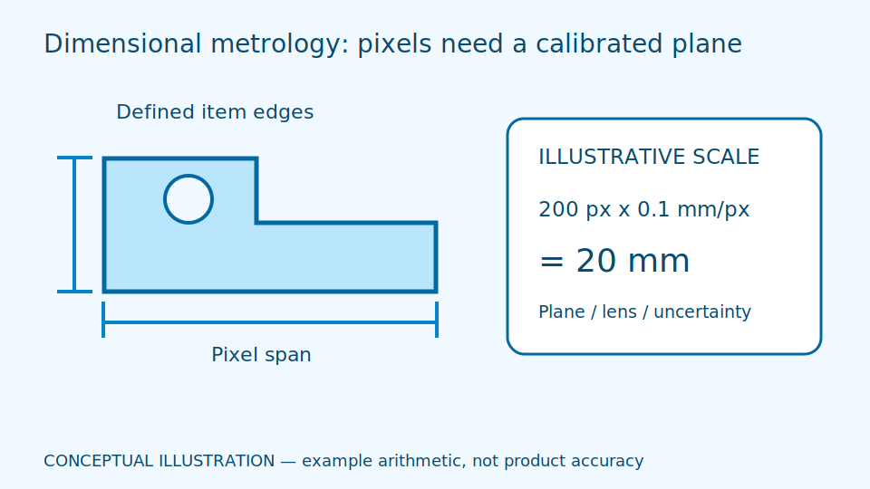
Pixels are image points, not inherently millimetres. An object closer to the camera appears larger. Lens distortion is deformation introduced by the lens; a datum is the reference point or line specified by the drawing. Measuring a hole relative to an outer edge using different datums can give different numbers even with clear images. Establish what distance to measure and its reference before choosing the highest pixel-count camera.
An uncertainty budget lists sources such as edge detection, scale, temperature and placement. A jig improves repeatability but adds tooling. Free-placement measurement requires position compensation and further error assessment. Choose according to the drawing's tolerance, or acceptable range, and have a measurement specialist approve the decision rule near limits. Many decimal places do not justify passing an item when uncertainty is unknown.
Scroll the diagram horizontally to inspect all details.
Illustrative Design Scenario
Illustrative design scenario: measure hole spacing on a plate held in a jig, using a reference in the same plane. Reject measurements when the plate lifts off the jig rather than retaining a scale invalidated by perspective.
For hypothetical numbers, a drawing accepts 20.0 plus or minus 0.1 millimetres. The image result is 20.08 with assessed uncertainty of plus or minus 0.05. Its interval, 20.03 to 20.13, overlaps the acceptance boundary at 20.10. Apply the agreed decision rule or hold for review; do not claim a pass just because the central value is below the limit.
Operators could modify the jig to maintain a fixed plane or choose a method accommodating different heights. The former is simpler but restricts shapes; the latter is more complex and needs fresh reference checks. Trial standard artefacts at several positions and have a measurement specialist repeat checks. Do not damage products or alter production machinery outside specifications to create examples.
Inputs and Prerequisites
Provide drawings, datums, tolerances, traceable reference artefacts, temperature ranges and fixture repeatability records. Specify whether the task needs planar measurements or actual three-dimensional geometry.
A traceable reference has evidence linking it to measurement standards. Record the drawing revision, lens, focus and calibration date. Repeatability describes closeness of repeated measurements under the same conditions, not agreement with the true value.
Results should include distance, unit, datum, uncertainty and image conditions, with a no-measurement status for an incorrect plane. Never show zero for an undetected edge: someone could use it for a dimensional decision without noticing the limitation.
Trial and Integration Workflow
- 1Calibrate the camera and verify the reference plane with a standard artefact.
- 2Define edge detection and datums to match the drawing.
- 3Repeat across positions, operators and days, then construct an uncertainty budget.
Evaluation and Acceptance Criteria
Compare against reference equipment suitable for the tolerance. Report bias, repeatability and uncertainty. Define a decision rule near limits in advance instead of forcing pass/fail results when the uncertainty interval overlaps a tolerance boundary.
Bias is systematic difference from the reference. Closely repeated measurements may still be wrong in the same direction every time. Test several sizes, positions and people placing items, avoiding conclusions valid only at the image centre or for one part.
A measurement specialist should be able to reproduce the calculation and parameters from the same data. Check reference artefacts after focus or equipment changes. Do not continue accepting work on an old calibration after geometry changes; record why measurements were held.
Failure Cases and Limitations
Shadows, burrs and transparent edges can shift detected boundaries away from actual geometry. Different planes cannot share one scale. Calibration does not remain valid indefinitely after camera movement, focus changes or temperature changes.
Perspective changes apparent size with distance and angle. A two-dimensional image does not reveal every height. Moving from flat plates to three-dimensional shapes requires different methods and evidence, not extrapolation from accuracy in the original plane.
Uncertainty standards guide measurement; they do not certify the instrument or inspected product. Proposals for finer measurements must demonstrate the whole system, not present camera resolution as already delivered accuracy.
Scroll the diagram horizontally to inspect all details.
Practical Checklist
- Do the datums match the actual product requirements?
- Is the reference traceable and in an appropriate measurement plane?
- Is a decision rule defined for results near tolerance limits?