
Principles, Scenarios and Suitability
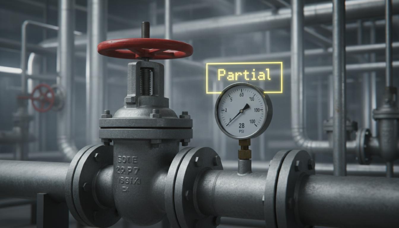
Handwheels, levers and indicators reveal external valve states, not proof that water or gas flow has stopped. Define whether the observation concerns an indicator or equipment pose, and retain an unknown state when it cannot be seen.
An indicator shows an external position; it is not a flowmeter. A lever may look closed while the internal mechanism is damaged or incompletely sealed. Multi-turn handwheel position may be unknowable from one image. Describe the visible indication, not confirmed isolation. Images support inspection rounds but do not authorise maintenance entry or opening pipes.
Define reference positions for the actual model and installation. A lever parallel to piping does not mean open for every design. Intermediate ranges avoid rounding borderline results but add manual work. Use open, closed, intermediate and unknown with images and time. Operators should compare with process data or suitable checks, not infer tight shutoff from an external angle.
Scroll the diagram horizontally to inspect all details.
Illustrative Design Scenario
Illustrative design scenario: inspect a valve lever with defined reference positions to support inspection rounds. Send intermediate positions for review rather than rounding them to open or closed or concluding that energy isolation is complete.
Suppose the lever changes but a downstream gauge still has a reading. Operators should check whether this means retained pressure or flow using approved procedures. Do not command valve movement from images or assume the gauge is faulty. State reading and energy-isolation verification are separate responsibilities with clearly assigned owners.
Options include showing the indicator from a better angle or using authorised position data from existing equipment. Neither alone confirms tight shutoff. Trial poses with demonstration equipment or safely obtained data. Do not operate critical production valves to create labels or reduce lockout/tagout procedures because a display says closed.
Inputs and Prerequisites
Provide valve types, reference positions, camera mounts, tags and definitions for open, closed, intermediate and unknown. Explain how each visible indication relates to the actual mechanism.
A tag identifies a specific valve. Check it against drawings and actual labels, with the model. Cameras seeing several nearby valves need reference locations, not selection of the clearest valve instead of the required one.
Results should show external state, time, image and uncertainty, explicitly leaving flow or isolation unconfirmed. Label old data as stale, not current inspection. After indicator replacement or mechanism repair, operators must confirm new reference positions before reusing criteria: external appearances may relate to actual positions differently after repair.
Trial and Integration Workflow
- 1Check that the position indicator is visible and associated with the correct tag.
- 2Estimate position using reference geometry for that valve model.
- 3Display the state and image, referring conflicts with process data for review.
Evaluation and Acceptance Criteria
Measure confusion across all states, including intermediate and unknown, with camera angles, occlusion and different models. Flow or tight-shutoff verification requires separate measurement and testing rather than inference from a lever image.
Confusion means mixing outcomes, such as calling intermediate closed. Report it separately because consequences differ from an unknown result. Test occlusion and camera movement using controlled data, not improve apparent confidence by discarding difficult images.
Operators should confirm position labels and review ambiguous results. Check display wording does not imply maintenance authorisation. Acceptance includes correct tag association and missing-data status, not pose-classification scores alone.
Scroll the diagram horizontally to inspect all details.
Failure Cases and Limitations
Multi-turn handwheels may not reveal position and indicators may be damaged. External state does not certify tight shutoff or isolation. Images do not replace lockout/tagout or authorise maintenance access on their own.
Lockout/tagout controls energy isolation under site procedures. Images cannot check every energy source or residual energy. Preserve procedures and responsible personnel; scores are not safe-opening evidence.
Additional valve models or command integration require separate study and risk assessment, not claims of existing valve control or certified protective loops. Never create leaks or hazardous conditions to test states.
Practical Checklist
- Is external position distinguished from confirmed tight shutoff?
- Are intermediate and unknown states available as outcomes?
- Do energy-isolation decisions still follow the prescribed procedures?