
Content Level: Overview / Implementation considerations
Principles and Suitability
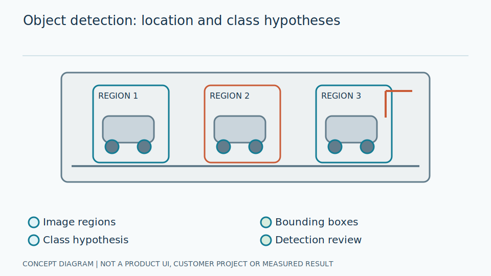
Object detection returns bounding boxes, classes and scores, not the instrument values inside those boxes. Lowering the confidence threshold often increases both target recall and false detections. Non-maximum suppression (NMS) handles overlapping boxes according to specified criteria.
A detector points out where objects of interest may be, providing a crop for later inspection. Its score reflects its trained response; it does not establish that a crop contains the entire unit or supports a reading. Finding a dial must be separated from confirming that its region is suitable for estimating pointer angle and converting it into a value.
NMS reduces duplicate boxes according to scores and overlap, but neighbouring objects can overlap without being duplicates. Define coordinate systems and restoration from resized or padded images. Establish how much surrounding space the reader requires. Box adjustments improving detection scores may harm reading if necessary details are clipped, so geometric completeness and detection overlap are distinct acceptance criteria.
Scroll the diagram horizontally to inspect all details.
Illustrative Industrial Example
Illustrative design scenario: a detector locates gauges on a panel and sends each region of interest to a pointer reader. Check crop quality first; an incomplete dial crop may omit the pivot, scale or measurement unit needed for interpretation.
Suppose a panel contains several gauges and circular objects that are not gauges. A detector may also box those circles. Passing every box to a reader without checking can produce lines and plausible numbers from the wrong object type. Verify scale and unit completeness, recording rejection reasons to distinguish detection errors from genuine reading failures within correct crops.
If tiling reveals small gauges, restore coordinates to the full image and carefully merge duplicates at tile boundaries. Check conversion with box overlays before testing the reader. Link boxes to equipment positions using a verifiable procedure, not model output order as gauge names. That order can change even on an unchanged panel, creating incorrect identities despite otherwise correct detections.
Study and Trial Workflow
- 1 Agree on dial-box boundaries and classes so annotators use consistent definitions.
- 2 Test image sizes and tiling strategies for small gauges.
- 3 Tune confidence and NMS on validation data, including overlapping gauges and gauge-like backgrounds.
Evaluation and Metric Definitions
Measure precision, recall and AP by target size, and count crops that are sufficiently complete for the reader. A detector confidence score must not substitute for the probability that the instrument value was read correctly.
A box meeting overlap criteria can still omit a unit at the dial edge. Define additional reading-region requirements, such as pivot and working-scale visibility. Report how many correct boxes genuinely support reading, and whether false boxes produce values that should not exist. Otherwise evaluation stops at location and hides damage introduced downstream by accepting incomplete or incorrectly typed regions.
Break results down by size and gauge count, including adjacent targets and image edges. Compare before and after NMS to distinguish targets never proposed from targets deleted during suppression. Include image preparation and tile merging in timing; one tile's inference time is not whole-system latency. Retain resizing conditions so comparisons between versions use equivalent visual evidence.
Limitations and Failure Cases
Small gauges and reflections may cause misses. Heavy box overlap can make NMS remove neighbouring gauges, while resizing can erase thin pointers. Detection quality must therefore be checked together with crop usability.
Lowering thresholds can reduce misses while adding false boxes for inspection. More resolution adds detail and computation. Choose jointly with the reader, not from detection scores alone. If a gauge is so small that its unit is absent from the image, finding more boxes cannot provide the missing evidence needed for a defensible measurement report.
A box is not a permanent equipment identifier. Camera movement or panel changes can invalidate position-to-tag mappings. Check panel consistency and allow unmatched results rather than forcing the nearest gauge assignment. Retain unmatched-image evidence under the data policy. Detection is one stage of image reading, not confirmation of machine condition or readiness to issue control commands without further application assessment.
Practical Checklist
- Does the region of interest contain the complete scale and unit?
- Have clocks and other circular objects been tested as false-positive cases?
- How is each detected box linked to a verified instrument tag?