
Principles, Scenarios and Suitability
Assembly and kitting inspection compares component presence, quantity, orientation and position against the correct product BOM. It suits clearly visible elements, but an external image cannot establish tightening torque, electrical connections or the condition of internal fastenings.
A BOM is the bill of materials required for a product model; a kit is the set prepared before assembly, and a recipe is that model's inspection rules. Think of gathering ingredients for a recipe: having everything for the wrong recipe still gives the wrong result. Check model, quantity and orientation separately. Complete does not mean correctly assembled or functional in every respect.
Engineering requires a reference tray position and a tolerance, the acceptable range of variation. Firmly locating the tray helps positioning but restricts operation. Flexible inspection reduces placement requirements but risks confusing similar components. Choose according to product variety and ask assemblers to review borderline cases. Retain an unknown result for an invisible compartment rather than guessing that a component lies beneath another.
Scroll the diagram horizontally to inspect all details.
Illustrative Design Scenario
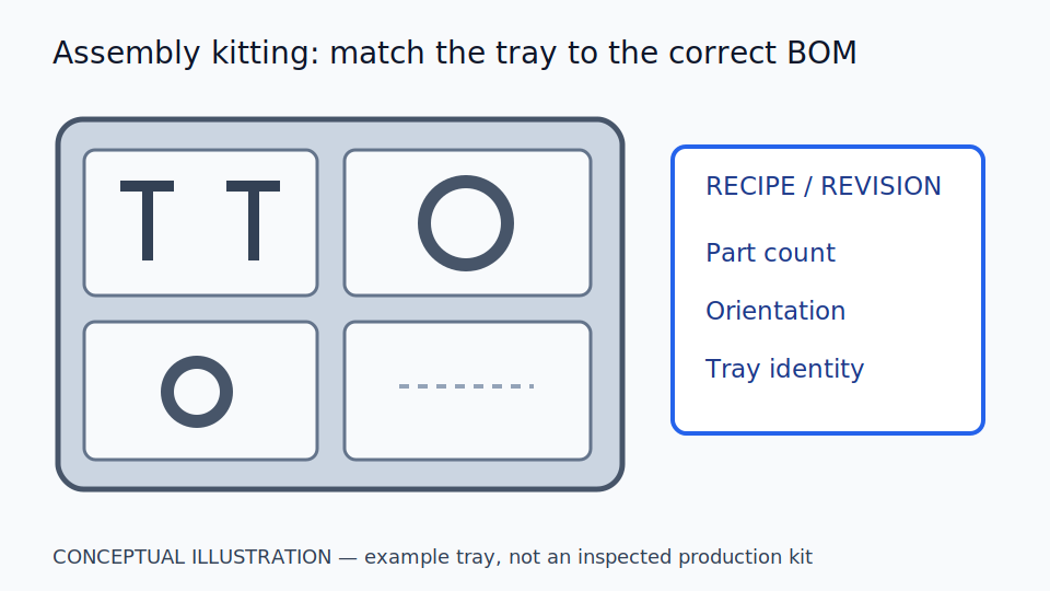
Illustrative design scenario: a kit tray has screw and seal compartments for each product model. A production-order code selects the inspection recipe. If the model code is unreadable, hold the tray for human review rather than selecting the closest recipe.
In a hypothetical case, model A needs four screws and one seal, while model B needs six screws. Even a clear image of four screws cannot support a decision until the model is known. Read the job code or have staff select from a confirmed production order. Selecting a recipe from the visible quantity could misinterpret a shortage as a model requiring fewer parts.
When seals overlap, an operator could change the tray compartments to separate them or add a camera angle. Tray changes improve visibility but add tooling; multiple views add inspection time. Have a reviewer confirm the physical components and record why the job was held. Assembly-line integration trials should use test trays and shadow results, not release incorrect kits into real products to prove detection.
Inputs and Prerequisites
Prepare BOMs, component images by model, position tolerances and examples of missing, extra, reversed or overlapping parts. The inspection trigger must be associated with the tray identifier.
Record the BOM revision and effective date, together with images of components with similar materials or colours. A trigger starts inspection and must remain linked to the same tray throughout its route. Do not apply the latest image result to every passing tray.
Results should identify the model, compartment, visible quantity and incomplete-view status, with image evidence. Seeing a component does not confirm its material code. Where internal specifications matter, use codes or supplementary inspection methods required by the job specification.
Trial and Integration Workflow
- 1Confirm the recipe and product-model identifier before checking components.
- 2Align the tray to its reference and inspect every compartment against the BOM.
- 3Send results with evidence and route obscured compartments for reinspection.
Evaluation and Acceptance Criteria
Measure misses and false rejects separately by component and error type. Test model changes and similar-looking parts, including result-to-tray matching at actual operating speed. Individual image scores do not establish that a complete kit has been checked.
A miss is an undetected error; a false reject is a correct kit rejected. Assess the whole tray: reading almost every compartment correctly may still release a kit missing a critical component. Reserve testing data from days and trays not used for training.
Have assemblers review held results and sample passed kits. Record their observations when the BOM changes or a code is unreadable. Test delayed results and exchanged trays in a test environment to verify matching rather than relying on image scores alone.
Scroll the diagram horizontally to inspect all details.
Failure Cases and Limitations
Overlapping parts and opaque bags can prevent counting. Parts with the correct shape but the wrong material specification may look identical. Image inspection does not replace torque or functional tests required by the assembly specification.
Torque tests assess tightening torque; functional tests assess operation. Both answer questions external images may not answer. Extending from kitting to assembly inspection requires redefining what is actually visible and the routes for other inspections.
Images may capture assemblers' hands or faces. Frame only the tray and limit retention. Do not automatically use results to accuse a worker of wrongdoing. Multiple-model recipes are a proposed study approach, not a claim that every model is already supported.
Practical Checklist
- Is the recipe linked to a confirmed product-model identifier?
- Are extra and missing components tested separately?
- Is there a reinspection route for obscured components?